Yagi Directional 2.4ghz 802.11b Antenna
Dipole and Placement

Home

Getting Started | Dipole placement | Putting it all together | Finishing touches | Testing it out | Contact Me

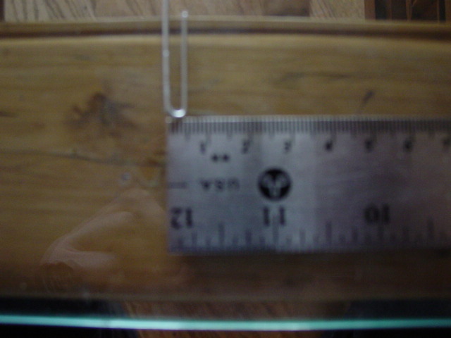
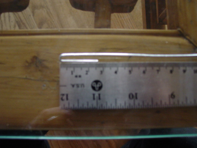
This antenna is called a yagi directional.It requires 4 elements.Two of them are called directors that help collect and "direct" the radio waves.The third is called a dipole which is used to transmit and recieve the signal.Lastly there is the reflector.Take your time when you are straightening your paperclips.The measurements are in millimeters and centimeters.These measurements were found at this site:
http://jj.dormard.free.fr/Frisko.htm

measure.jpg

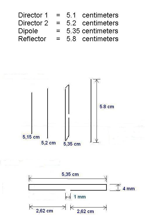
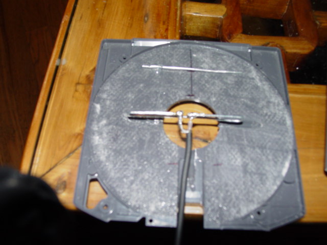
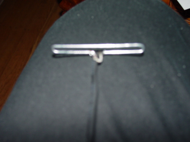
When bending your paperclip for the dipole make sure you take your time as 4mm is difficult to get right the first time.I have soldered my coaxial cable to the dipole.

measuredipole2.jpg

measuredipole1.jpg

spacing.jpg

The spacing for each element is as follows:
director to director is 1.5cm
director to dipole is 1.5cm
dipole to reflector is 2cm

I originally drew out the layout of elements on the disk.When I started gluing these in place,I realized it was just easier to start with the dipole which was centered over the existing hole.And then use a ruler for exact placement.

dipole.jpg

This picture is a little fuzzy.But I have soldered the center wire to one end of the dipole and the braid has been soldered to the other end.I actually did this step twice.Make sure you solder the coax on top of the bottom of the dipole.(Where the space is.)